Sign Convention
The program uses three right-handed coordinate systems:
1. Global Coordinate System
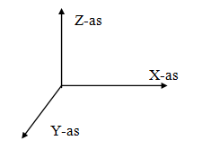
The position of this global coordinate system is arbitrary. The XY plane coincides with the plane of the frame. This coordinate system is used for defining node coordinates, node constraints and node loads. Calculated node deformations and support reactions are displayed relative to this coordinate system.
2. Member Coordinate System
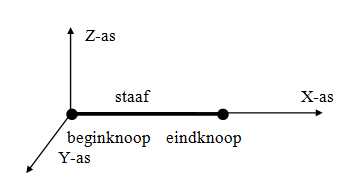
The origin of this coordinate system is always at the start node of the member in question. The XY plane coincides with the plane of the frame. The X-axis coincides with the member axis.
3. Node Coordinate System
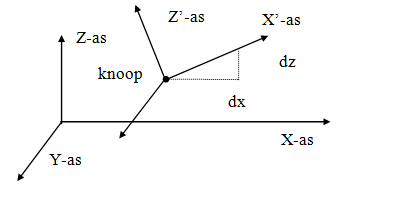
A local (node) coordinate system can be specified. The origin is at the node in question. The direction of the X-axis is determined by specifying a relative dx and dz from the node. Local coordinate systems can be used to specify node constraints (supports or 'restraints'), node loads and/or node displacements in any direction.
Sign Conventions
The input and output data are displayed relative to the coordinate systems described above.
- A force in the direction of the positive X or Z axis is considered positive.
- A moment rotating from the positive X-axis to the positive Z-axis (according to the corkscrew rule) is positive.
- A moment opposite to the 'clockwise direction' is positive.