Node Displacements

Node displacements are specified in a Node coordinate system. See Sign Convention.
The dialog box below opens.
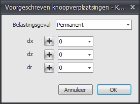
Load Case
Choice of the load case. Here you can also create a new load case directly.
The node displacement is entered in the global coordinate system by default. When a local coordinate system has been specified for the node concerned, the displacement is specified relative to that coordinate system.
Displacements
- dx - Magnitude of the displacement in mm in the x-direction
- dz - Magnitude of the displacement in mm in the z-direction
- dr - Magnitude of the rotation in mrad about the y-axis
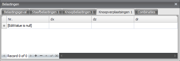
Table
Node displacements can also be added and/or changed in the table. It makes no difference. You can also switch between graphical input and tabular input at any time.